| Data name | ||||||||
| Improvenment of quality and accuracy, and cost reduction by vacuum chuck | ||||||||
| Overview | ||||||||
| In this work, the finished thickness was as thin as 4mm. So, it was difficult
to satisfy the surface roughness and processing accuracy. To solve the
problem, the vacuum chuck was used, and it reduced the cost. Processed nember:50/lot |
||||||||
|
||||||||
| Point | ||||||||
| Problems like clamp distortion, vibration, processing atrain were solved by vacuum chuck, and it enhanced processing accuracy, and connected to cost reduction. | ||||||||
| Result | ||||||||
| There was no vibration, clamp distortion or processing distortion at all,
and the processing has finished without problems. Machining accuracy in
thickness direction was less than 5μ. コCost was reduced by 41.8%.
・The setup time was reduced with one jig. ・Installation and removal time was shortened, because the processes such as the tightening of the bolts have disappeared. ・Before the improvement, restraint of the whole work was not uniform, so, vibration was significant, and it was impossible to improve the cutting condition. ・With the vacuum chuck, the entire workpiece is pressed uniformly, so, even if the cutting conditions were severe, there could be no vibrations. |
||||||||
| Commentary | ||||||||
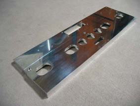
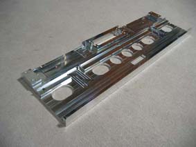
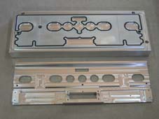
| Befor improvement, this work required five step processings, and the cost
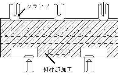
performance and quality of the product was bad. First and second steps Machining 135mm dimensions using vise(4 piles layered) The third step Processing of the item using the vice (above, left picture: round hole, elliptical hole, square hole to the point where it penetrates in the next process). Fourth Step Processing of the shaded area (the figure below) using the 5 clamps.
Processing of the shaded area (the figure below) using the four clamps.
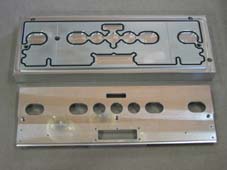
The machining processes could be reduced from 5 steps to 2 steps by usage of a vacuum chuck, and the jig was made to be commonly used in the 1 st and 2nd steps. In the first step Processing on the side of the work plane with three stopper pins on the jig.
In the second step 1In the first sotp of machining, we used φ8 seat grinding for positioning, then advanced on the engraved side and outer periphery machining.
|
||||||||
| Coment | ||||||||
| In most cases when using a vacuum chuck with a milling / machining center, the mounting base is specified for the workpiece. Since the clamping force of the vacuum chuck, when applied in the horizontal direction, is about 35% of the perpendicular direction, the stopper pin is set up in this base. In the base, an O-ring groove for preventing leakage, and a leak groove for improving exhaust performance are processed. Neoprene sponge round cord is used as a O-ring for leak prevention. Toyoron hose is used for the line between the vacuum unit and the base. This time, the base is processed using a machinen that processes the workpiece. |